Why Kelvin Connections Matter for Solar Cell I-V Testing
Learn how 4-wire Kelvin sensing eliminates measurement errors caused by lead resistance, and why it's essential for accurate solar cell characterisation.
When characterising solar cells, measurement accuracy is crucial! Small errors in voltage readings can significantly affect calculated parameters like fill factor, series resistance, and efficiency. One of the most common sources of error in I-V measurements is lead resistance, and the solution is Kelvin (4-wire) connections.
TL;DR: Standard 2-wire measurements include voltage drops across your test leads, making your devices appear worse than they truley are. 4-wire Kelvin sensing uses separate force and sense wires to measure the true device voltage, eliminating lead resistance errors. The miniSMU MS01 supports this natively using its dual-channel architecture.
The Problem: Lead Resistance
In a standard 2-wire measurement, the same wires that carry current to your device also measure the voltage. This creates a fundamental problem: Ohm's law dictates that the voltage drop across the lead resistance is included in your measurement.
Consider a typical setup with test leads having 0.1Ω total resistance. If you're measuring a solar cell producing 100mA at its maximum power point, Ohm's law tells us:
V_error = I × R_lead = 0.1A × 0.1Ω = 10mV
A 10mV error might seem small, but for a solar cell with Voc of 0.6V, this represents a 1.7% error relative to Voc, and the error grows with current. Around the maximum power point, where currents are near their highest, this voltage error can significantly affect the measured efficiency of your cell!
Use the interactive calculator below to see how lead resistance affects your measurements:
Lead Resistance Error Calculator
See how lead resistance affects your voltage measurements
At 27 mA through 1.00 Ω of lead resistance, you lose 27.00 mV to the wires instead of measuring it at your device.This error level can significantly affect fill factor and series resistance calculations. Consider using 4-wire Kelvin sensing.
How This Affects Your Results
Lead resistance errors don't just shift your I-V curve; they distort it in ways that corrupt your extracted parameters:
Fill Factor
The fill factor is particularly sensitive to voltage errors near the maximum power point. Lead resistance makes the I-V curve appear more "rounded", artificially reducing the calculated fill factor. A device with a true FF of 0.78 might measure as 0.74, a significant difference when comparing device performance.
Series Resistance
Lead resistance adds directly to your calculated series resistance. If you're trying to measure the intrinsic Rs of your solar cell to optimise contact metallisation, you'll be measuring your test setup instead of your device.
Efficiency
Since efficiency depends on Voc, Isc, and FF, errors in any of these find their way into your final PCE value. For research applications where you're tracking incremental improvements in device performance, this uncertainty can mask real progress (not to mention potentially knock down your paper's impact factor!).
The Solution: 4-Wire Kelvin Sensing
The diagram below illustrates the key difference between 2-wire and 4-wire measurement configurations.
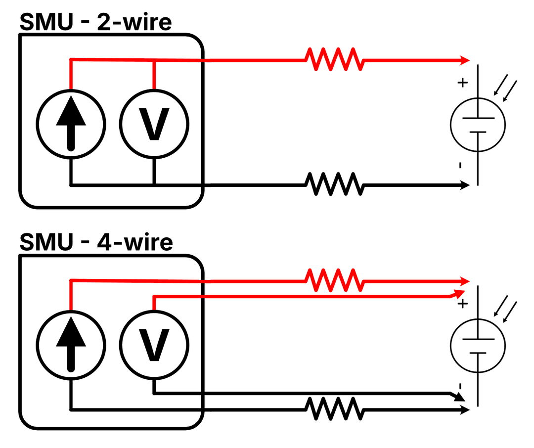
In a 2-wire setup, the current source and voltmeter share the same pair of wires. The voltmeter measures at the SMU terminals, so lead resistance (shown as the zig-zag resistors) is included in the voltage reading. Any current flowing through these resistances creates a voltage drop that corrupts your measurement.
In a 4-wire setup, the current source has its own dedicated force wires, while the voltmeter uses separate sense wires that connect directly at the device terminals. Because the sense wires carry essentially zero current (typically nanoamps for the miniSMU MS01), there's negligible voltage drop across their resistance; the voltmeter sees the true device voltage, regardless of how long or resistive the force wires are.
See the Difference
The interactive chart below shows how lead resistance distorts your measured I-V curve. The green curve represents the true device characteristics (what you'd measure with 4-wire sensing), while the red curve shows what you'd actually measure with 2-wire connections. Adjust the sliders to see how device parameters and lead resistance affect the measurement error:
2-Wire vs 4-Wire IV Curve Comparison
See how lead resistance distorts your measured IV curve
The green curve shows the true IV characteristic (4-wire measurement). The red dashed curve shows what you'd measure with 2-wire connections.
With 1.00 Ω lead resistance, the fill factor appears 2.5% lower than the true value, making your device look worse than it actually is.
Using Kelvin Connections with miniSMU
The miniSMU MS01 supports 4-wire Kelvin sensing using its dual-channel architecture:
- Channel 1 acts as the force channel, sourcing voltage and measuring current
- Channel 2 acts as the sense channel, measuring voltage with high impedance
When to Use 4-Wire Mode
4-wire sensing is recommended whenever:
- High currents are involved: The voltage error scales with current, so it's most critical near Isc
- Long or thin cables are used: Higher lead resistance means larger errors. Perhaps your solar cell is on the end of some long leads snaking inside a glovebox!
- You need accurate series resistance values: Essential for contact optimisation studies
- Comparing devices quantitatively: Eliminates setup-dependent variations
- Publishing or reporting results: Ensures your data reflects the device, not your cables
For quick screening measurements or relative comparisons where absolute accuracy isn't critical, 2-wire measurements may be sufficient.
Connection Setup
Connect your solar cell as follows:
| Terminal | Connection |
|---|---|
| CH1 HI | Device positive (current path) |
| CH1 LO | Device negative (current path) |
| CH2 HI | Device positive (voltage sense) |
| CH2 LO | Device negative (voltage sense) |
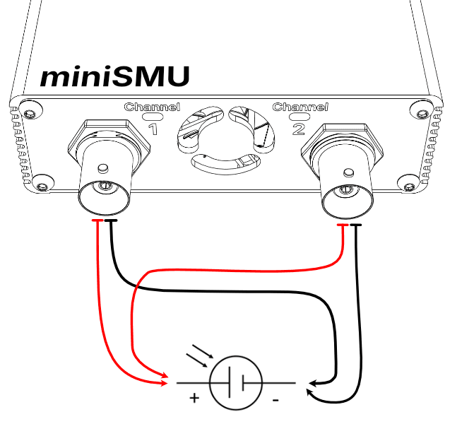
The sense connections (CH2) should be made as close to the device as possible, ideally directly at the contact pads or terminals.
Enabling 4-Wire Mode
4-Wire mode is available in the miniSMU App, via the minismu_py Python library, or by issuing commands directly.
In the miniSMU App:
- Connect to the miniSMU's port
- Navigate to the "About" tab
- Enable 4-Wire Mode
- Channel 2 will automatically be configured for high-impedance sensing when channel 1 is active for measurements
When 4-wire mode is active, the app displays the true device voltage from Channel 2 while Channel 1 handles the current measurement. Use of channel 2 as a separate SMU channel is disabled whilst 4-wire mode is active.
Python API
If you're automating measurements with Python using the minismu_py library, enable 4-wire mode with:
from minismu_py import SMU

smu = SMU()
smu.connect("COM3")  # Replace with your port

# Enable 4-wire Kelvin sensing
smu.enable_fourwire_mode()

# Configure CH1 for voltage sourcing
smu.set_mode(1, "FVMI")

# Run an I-V sweep - returns CH1 current + CH2 voltage
result = smu.run_iv_sweep(
    channel=1,
    start_voltage=-0.1,
    end_voltage=0.7,
    points=100,
    dwell_ms=50
)

# Disable 4-wire mode when done
smu.disable_fourwire_mode()
You can also query the current 4-wire mode status:
if smu.get_fourwire_mode():
    print("4-wire mode is active")
Direct SCPI Commands
For direct serial communication or integration with other tools, the miniSMU accepts the following SCPI commands for 4-wire mode:
| Command | Description |
|---|---|
SYST:4WIR ENA | Enable 4-wire mode |
SYST:4WIR DIS | Disable 4-wire mode |
SYST:4WIR? | Query status (returns 1 if enabled, 0 if disabled) |
When 4-wire mode is enabled:
- CH1 acts as the force channel (sources voltage, measures current)
- CH2 acts as the sense channel (high-impedance voltage measurement)
- Measurements on CH1 return CH1 current combined with CH2 voltage
OUTP1 ON/OFFcontrols both channels together
Practical Tips
Minimise Sense Lead Pickup
While sense leads don't carry current, they can pick up noise. Keep sense wires:
- Twisted together or shielded
- Away from power cables and switching electronics
- As short as practical
Connect Sense at the Device
The benefit of Kelvin sensing is lost if you connect the sense wires to the same point as the force wires. Ensure sense connections are made at the device terminals, not at an intermediate junction.
Verify Your Setup
A quick way to verify 4-wire mode is working: measure a known resistor with both 2-wire and 4-wire modes. The 4-wire result should be lower by approximately your lead resistance.
Summary
For accurate solar cell characterisation, 4-wire Kelvin sensing eliminates a significant source of systematic error. The miniSMU's dual-channel design makes implementing Kelvin measurements straightforward, giving you confidence that your I-V curves and extracted parameters reflect your device performance, not your test setup.
Happy measuring!